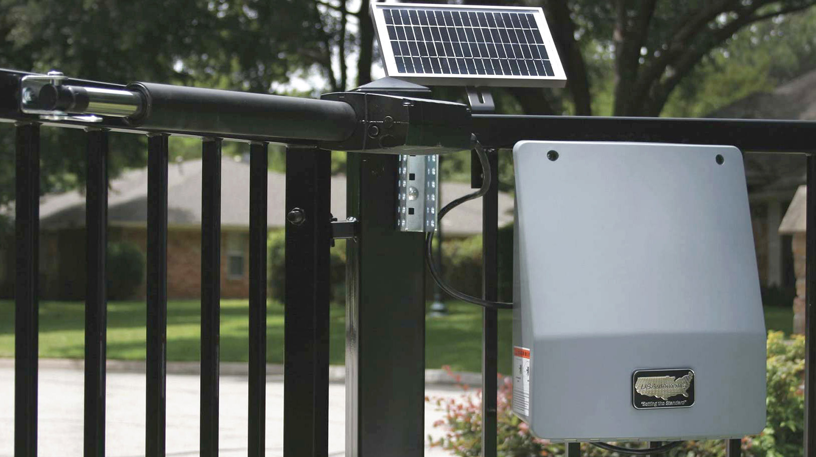
Sentry Double Gate Opener Installation Guide

Parts Needed:
620112 Bolt on Hardware - (1)
610105 CE Gate Bracket - (1)
610534 Sentry Manual Release Pin - (1)
610535 Clip for Manual Release Pin - (1)
630035 Sentry 300D 50' Cable - (1)
510300 Sentry Linear Actuator - (1)
630045 Sentry 300D Junction Box - (1)
610530 3/8" Bronze Bushing - (2)
610528 Sentry Nylon Washer - (2)
Pre-Installation:
The Gate 2 Kit will contain a linear actuator with a 1¼" hole plug, 50 feet of 5 conductor cable, wire nuts, junction box, and all necessary mounting hardware. The Sentry Control Box is equipped with two knock out ports for running the Gate 2 linear actuator cables. One knock out port is 1¼" and is intended for non-conduit installation (not suggested). The other knock out is ⅞" and designed for ½" conduit fitting for conduit installation (recommended). If conduit is being installed, knock out the ⅞" hole. If conduit is not being installed, knock out the 1¼" hole. Remove the knock out that is right for your desired installation.
Installing Gate 2 Linear Actuator
- Install Gate 2 Linear Actuator Using The Same Procedure Followed During Gate 1 Actuator Installation.
The linear actuator for Gate 2 comes with an 8' cable that must be cut and spliced in the following manner once linear actuator is installed.
Once Actuator 2 Has Been Installed:
- Locate the linear actuator cable connector and measure 18" from connector end and cut.
- Save 8 pin connector and pigtail for Step 20.
- Install junction box on Gate 2 hinge post below linear actuator using 2 self tapping metal screws.
- If conduit is being installed, attach 1/2" conduit adapter to the control box 7/8" knock out.
- Route linear actuator cable to junction box and determine specific length needed.
- Cut cable longer than needed for future considerations.
- Remove 2" of cable insulation to expose the 5 wires (Caution: Do Not Damage Internal Wires)
- Remove approximately 1/2" of insulation from each wire.
- If installing conduit, attach 1/2" adapter to junction box. If not, cut rubber knock out (supplied) to fit cable.
- Install Gate 2 extension cable into the junction box.
- Using supplied wire nuts, connect the 5 wires to the matching wire colors.
- Do not install junction box cover until all connections have been completed.
- With extension cable now installed in junction box, route the other end of the extension cable to the control box.
- Install wires into control box wire compartment.
- Snap 1 1/4" hole plug into control box if conduit was not used.
- Cut extension cable to length allowing for future considerations.
- Remove 2" of cable insulation to expose the 5 wires (Caution: Do Not Damage Internal Wires)
- Remove approximately 1/2" of insulation from each wire.
- Locate 8 pin connector and pigtail previously cut from Gate 2 linear actuator cable. Prepare wires for splicing.
- Connect the 5 wires from extension cable to the 5 wires from the pigtail by matching the wire colors. Then secure with supplied wire nuts.
- Roll cable and place in wire compartment.
- Install junction box cover and securely snap in place.
Connecting Gate 2 Linear Actuator To Control Board:
- Loacte the power connector attached to the linear actuator cable (red and black wires).
- Connect it to the remaining Plug N Go harness linear actuator power plug. These connectors are designed so that incorrect connection is not possible and it does not matter which connector is used.
- Locate the linear actuator cable 8 pin plug. Connect it to the Gate 2 connector located on the Sentry Control board adjacent to the Gate 1 connector. Securely snap in place. Once all connections are made, place wires in wire compartment.
Preparing To Operate Gate 2 For The First Time
Using the "Open/Close Command" button on the control board, open Gate 1. This is done because Gate 2 was just installed in the open position and now both gates will be in the open position.
Operating Gate 2 For The First Time And Final Adjustments:
- Locate the control switches and turn on switch 4 (press down on the right side).
- Gate 1 and Gate 2 should be in the open position if installed correctly.
- Press the "Open/Close Command" button to close Gate 1 and Gate 2.
- Gate 2 limit adjustment has not been made so it should stop short of fully closed.
- Turn "OFF" control switch 3, disabling Gate 1.
- Now use the "Open/Close Command" button to cycle Gate 2 and adjust Gate 2 close limit to match Gate 1 close position.
- With both gates now closes, turn "ON" control switch 3, enabling Gate 1.
- Press "Open/Close Command" button to open both gates and then close, adjust limit positions if necessary.
