Single or Dual Gate Will Not Operate
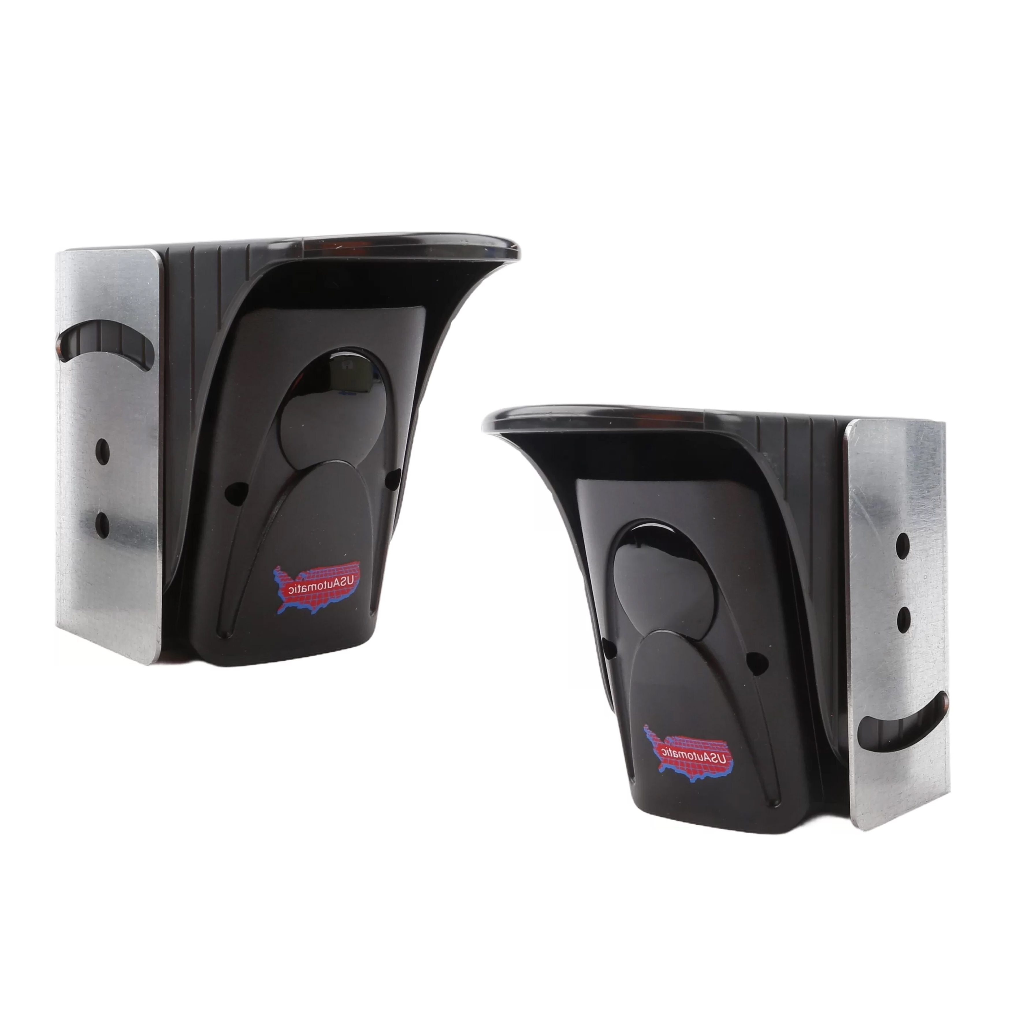
Contact Edge with 10K Resistor Monitoring
- Verify that dip switch SW1 switch 10 (contact edge monitor) is ON, pressed down on the right-hand side.
- Press and hold the LED indicator button on the control board.
- Verify that the LD3 LED (contact edge 2nd entrapment) located below the J2 plug is OFF.
- If it is ON, check the wire connections from the contact edge for proper connection.
- If the wiring is good, verify that the contact edge has an 8.25k or 10k resistor installed. Confirm by disconnecting and checking with a meter.
- Activate the contact edge by depressing it and verify that the LD3 LED turns ON bright.
- If it does not, the contact edge needs replaced.
Photo Eye N/C Contact Monitoring
- Verify that SW1 dip switch 10 is ON, pressed down on the right-hand side.
- Verify that dip switch SW1 switch 7 or 8 (photo eye monitor) is ON, pressed down on the right-hand side. Turn on the ones being used.
- Turn dip switches SW1 3 and 4 OFF to allow power to be applied to the photo eye.
- Press and hold the LED indicator button on the control board.
- Verify that the LD4 or LD5 LED (photo eye N/C) located below J2 on the control board is ON.
- If not, verify alignment between the photo eye transmitter and receiver. Correct if necessary.
- If alignment is good, check the wire connection from the photo eye for proper connection.
- If LD4 or LD5 are ON, verify that the LED turns OFF when the photo eye beam is broken.
- If the LED does not turn OFF when the beam is broken, the photo eye needs replaced.
Installation & Troubleshooting Guide