


How to Wire a Premium Metal Hardwired Keypad to a USAutomatic Gate Opener
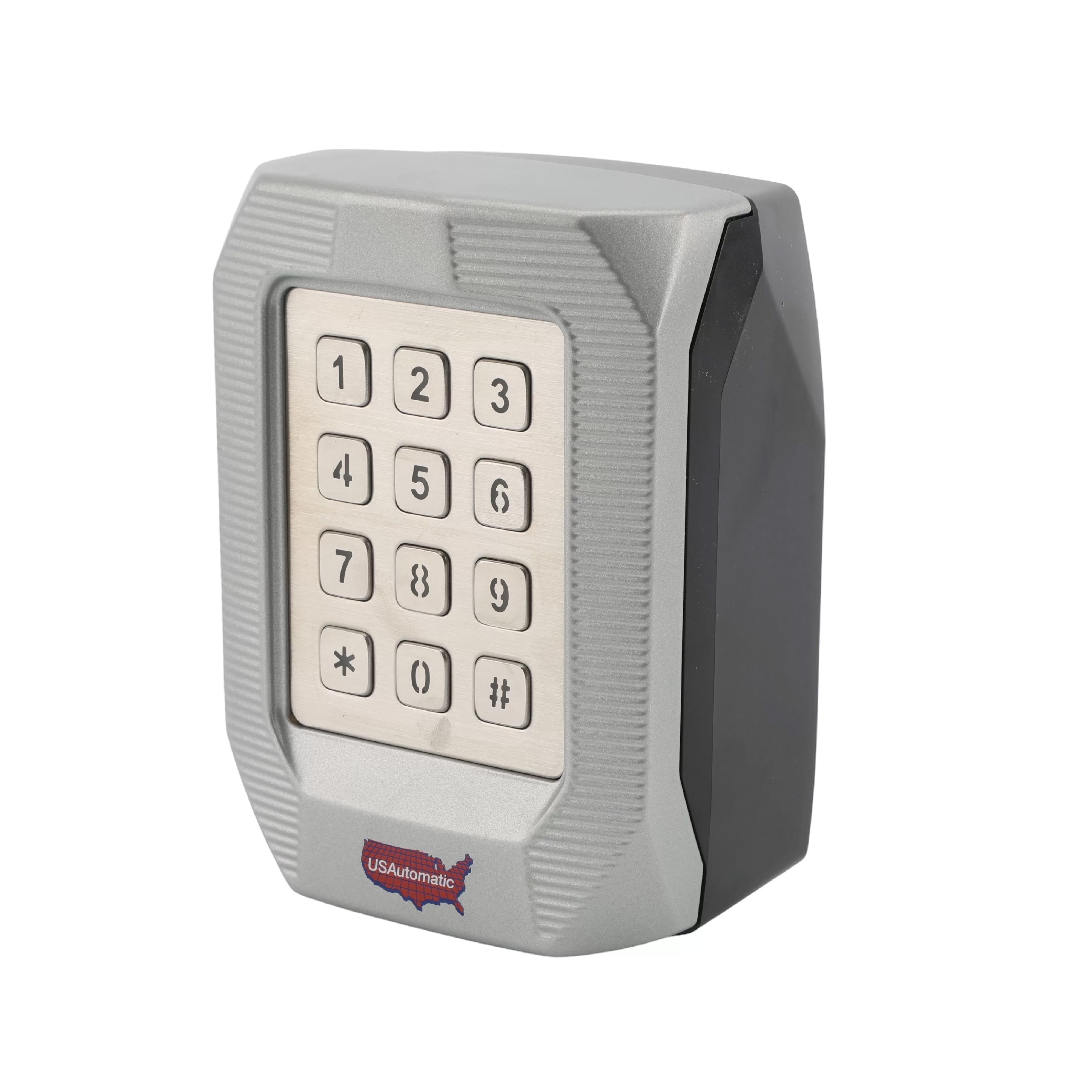
The Premium Metal Keypad for USAutomatic Gate Openers is an access-control device that enables secure operation of a gate automation system. This keypad can store up to 1000 permanent or temporary access codes. It requires 2-5-digit access codes and 1 master code as well. Using a keypad allows for property access management without requiring someone to verify authorization.
This article is a how-to guide that walks you through properly wiring the 050700 Premium Keypad. This access control device has two relays that can be connected to the board. Connections can be made in various ways to achieve a variety of functions. In this guide, we will cover common use cases for a gate opener in which the first relay can open or close the gate, and the second relay can keep it open.
The wires are not included with the keypad; therefore, you can use either 4 wires between the opener and keypad with jumper wires inside the keypad, or 6 wires running between the opener and the keypad.
You can review the full manual for the 050700 USAutomatic Premium Hardwired Keypad here:
Premium Metal Keypad Manual Shop the 050700 Premium Metal KeyboardMaterials Needed for Wiring
- 4- or 6-conductor wires for connecting the keypad to the control board in the gate opener.
- Wire cutters to create jumper wires (if only using 4 wires).
- A small flat-headed screwdriver.
Wiring with a 6 Conductor Cable
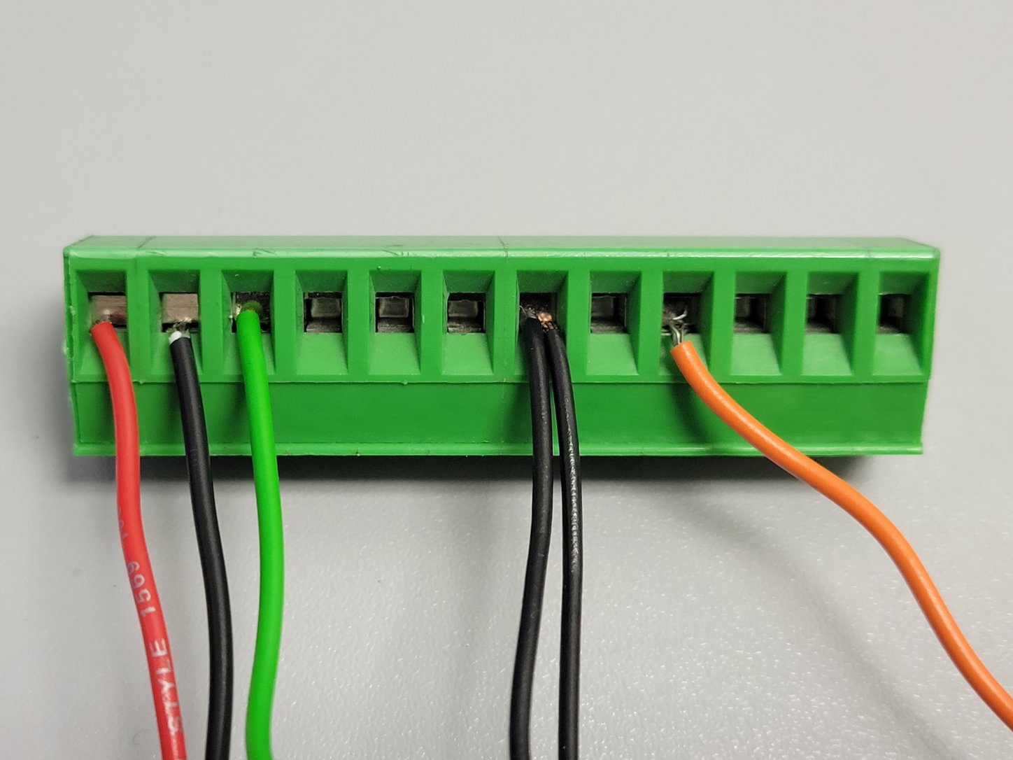
**Note: The images provided are for reference, and the wire colors do not need to match the image.
- Insert a wire into each of the following terminals:
- Positive + (#1)
- Negative - (#2)
- R1 NO (#5)
- R1 Com (#6)
- R2 NO (#8)
- R2 Com (#9)
- Insert each wire into the control board's J2 according to the table below:
| Keypad Terminal | J2 Terminal |
|---|---|
| Positive (#1) | J2 Terminal #1 |
| Negative (#2) | J2 Terminal #2 or 7 |
| R1 NO (#5) | J2 Terminal #3 |
| R1 Com (#6) | J2 Terminal #2 or #7 |
| R2 NO (#8) | J2 Terminal #9 |
| R2 Com (#9) | J2 Terminal #2 or #7 |

Wiring with a 4 Conductor Cable
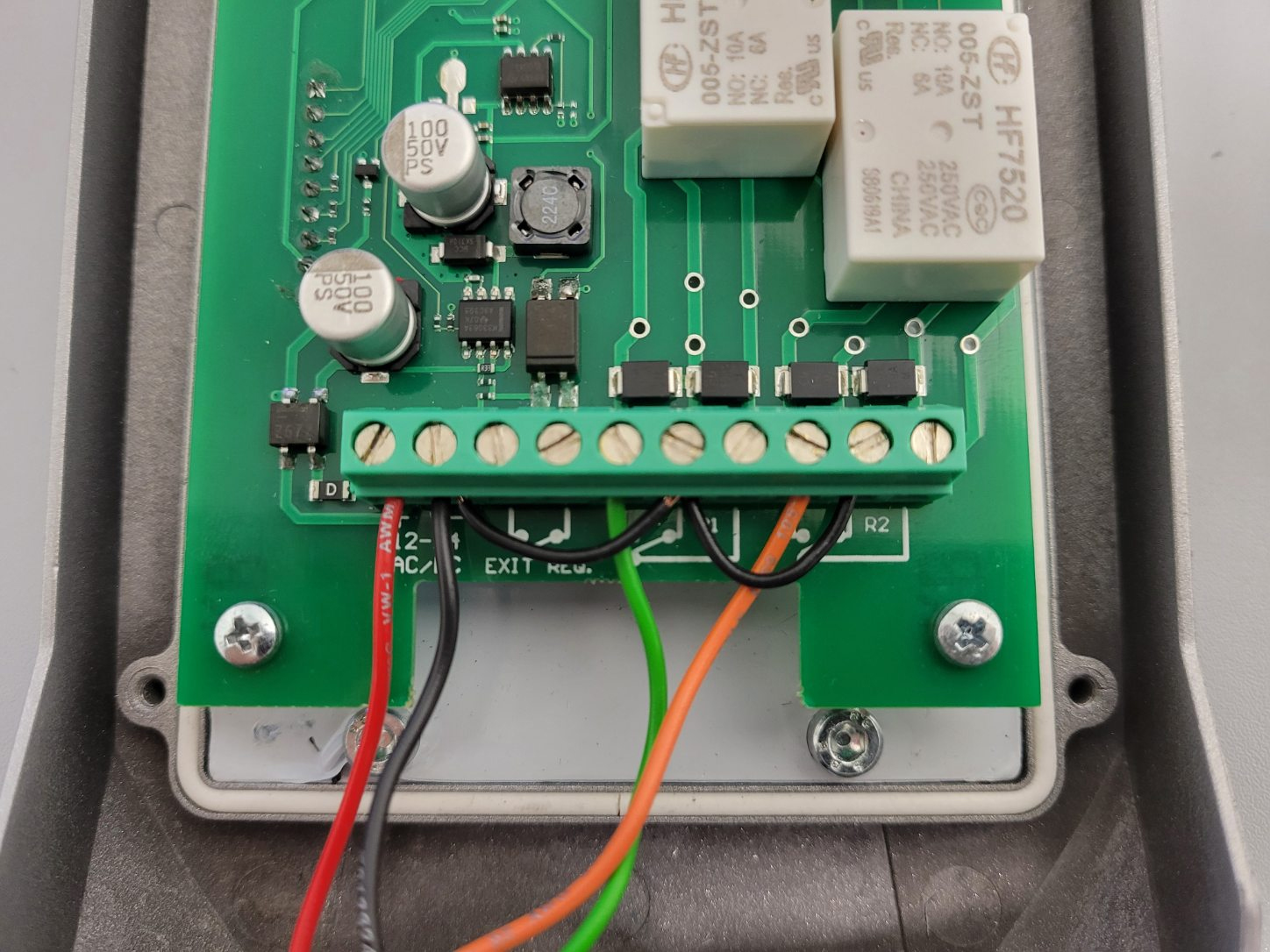
For wiring with a 4 Conductor Cable, jumper wires are used at the back of the keypad to bring together all ground and common connections into one wire that runs back to the board.
Again, the images provided are for reference, and your wire colors do not need to match them.
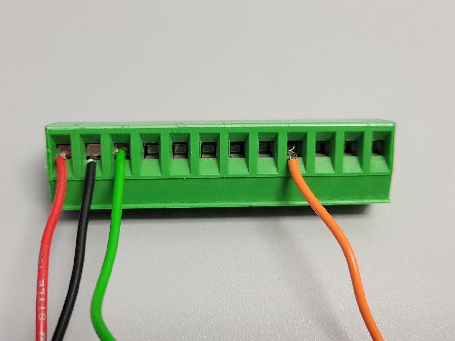
- Insert a wire into each of the terminals:
- Positive + (#1)
- Negative - (#2)
- R1 NO (#5)
- R2 NO (#8)
- Insert a small jumper wire between each terminal pair
- Negative - (#2) to R1 Com (#6)
- R1 Com (#6) to R2 Com (#9)
Insert each wire into the control board’s J2 terminal using the table below as a reference
| Keypad Terminal | J2 Terminal |
|---|---|
| Positive (#1) | J2 Terminal #1 |
| Negative (#2) | J2 Terminal #2 or 7 |
| R1 NO (#5) | J2 Terminal #3 |
| R2 NO (#8) | J2 Terminal #9 |
Need Further Guidance?
If you need some further assistance with wiring your keypad, contact our expert sales team. We'd be happy to walk you through the process and give you any guidance you may need for your USAutomatic Gate Opener or Gate Opener Accessories.
Contact Us