


How to Verify USAutomatic Photo Eye Alignment Using Test Points
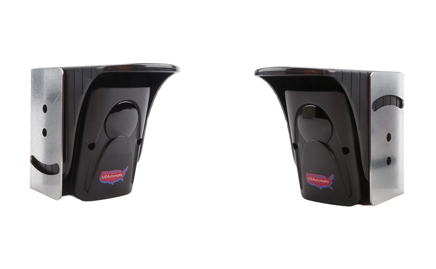
The photo eyes that come with USAutomatic Gate Openers come with test points that allow you to measure the alignment strength between the transmitting and receiving photo eyes. Proper alignment is essential for a safe and secure gate operator system. The transmitting photo eye emits a beam of light that is detected by the receiving photo eye; when that beam is interrupted, it triggers the gate opener to stop or reverse, protecting the obstruction and the gate opener from damage. Without proper alignment, the photo eye will not detect an obstruction.
It's important to note that although the transmitting photo eye has the capability of being hardwired for power, a lot of installations utilize the 3.6v AA batteries. When the batteries begin to die, the IR beam will weaken, and if the photo eye alignment is not done correctly, they will lose alignment much faster than the batteries are rated for. If you get the alignment strength as close to the maximum as possible, it will ensure the batteries last as long as they are capable of.
View the 550011 Through Beam Photo Eye Manual Here:
USAutomatic Thru Beam Photo Eye ManualAligning the Photo Eyes Using Test Points
What You Need:
- Small Phillips Head Screwdriver
- Voltage Meter – Capable of Reading DC Voltage
Identifying Test Points:
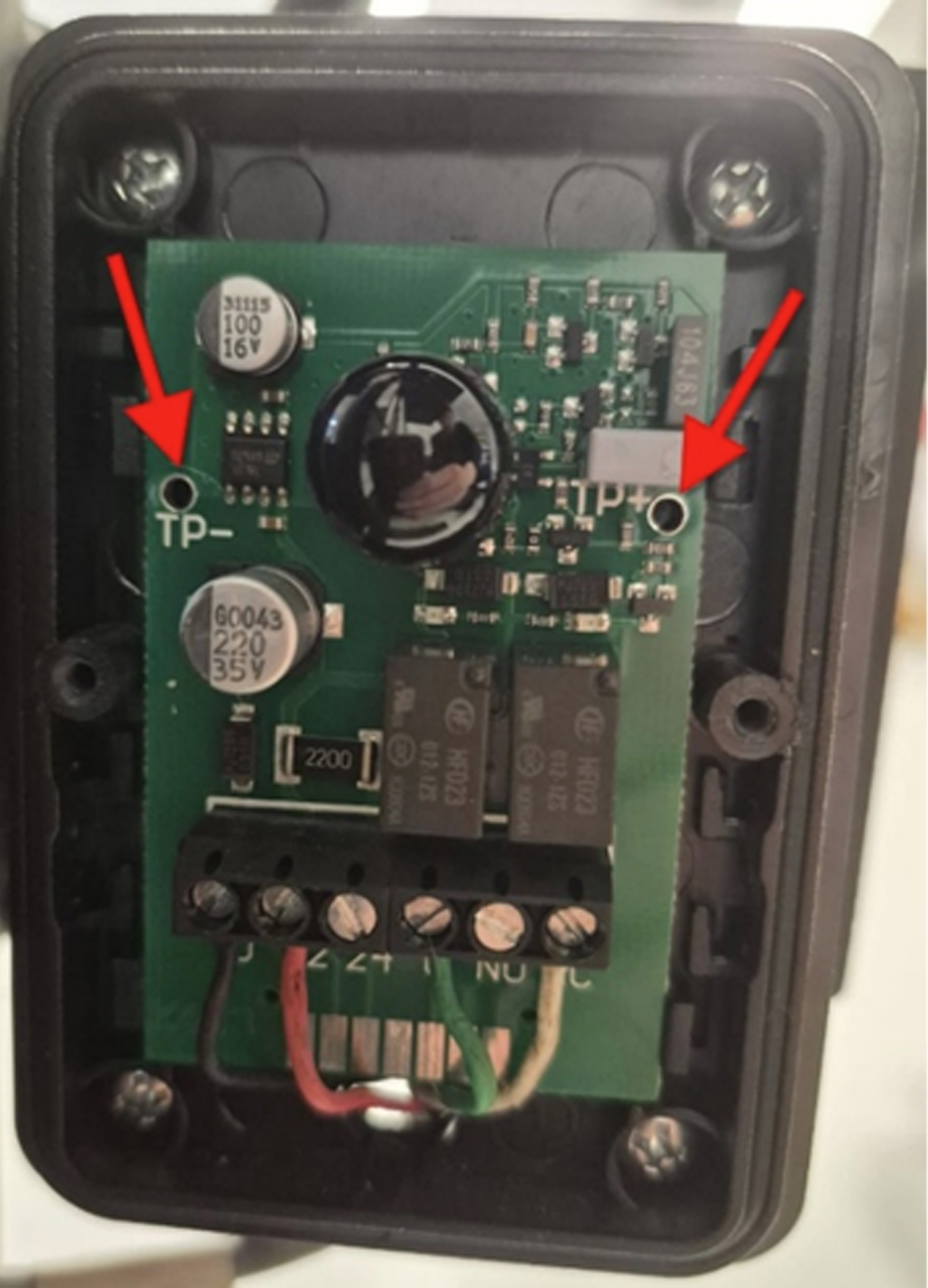
Remove the cover of the photo eye to reveal the internal structure and locate the test points. You can find the test points used to measure alignment strength at the left-center and right-center of the receiving photo eye. They will be labeled as "TP+" and "TP-". See the photo for reference.
Measuring the Test Points:
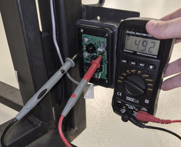
- Set your voltmeter to DV voltage.
- Insert the positive lead into the “TP+” test point.
- Insert the Negative lead into the "TP-"test point.
The leads should be able to hang free where they contact the photo eye so you can step away for the photo eyes to realign.
Adjusting the Photo Eye Alignment:
There are two alignment indicator LEDs on the receiving photo eye:
- Red means the eye is not aligned.
- Green means the eye is aligned.
Make adjustments to the photo eyes as needed to achieve as close to 5v as possible.
- The minimum alignment strength is 3v.
- The maximum alignment strength is 5v.
Check out the chart below for reference when aligning your photo eyes:
| TP-/TP+ readings (DCV) | Signal Strength | Alignment |
|---|---|---|
| 0 Vdc | No Signal | NOT Aligned |
| 3 Vdc | Minimum useful signal | POOR Alignment |
| 5 Vdc | Maximum useful signal | STRONG Alignment |
Shop the USAutomatic Thru Beam Photo Eyes
Contact Our Expert Sales Team for Further Assistance
If you need some additional guidance when aligning your USAutomatic Gate Openers, contact our expert sales team! We will be happy to walk you through the process and provide any information you may need regarding your USAutomatic Gate Opener Equipment.
Contact Us