


How to Measure the Potentiometer on a Ranger HD Actuator
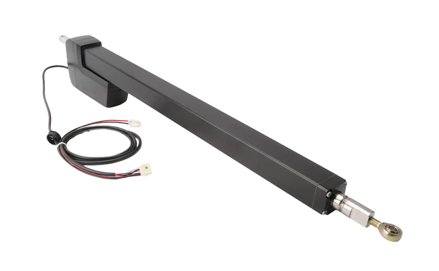
This informational guide will take you through how to test the potentiometer (POT) on a Ranger HD actuator. This test can be performed whenever the gate operator stops at the wrong position or travels in the wrong direction. By comparing the POT readings against the actuator's stroke length, you can determine whether the actuator arm is causing the limit errors. Keep in mind these sorts of issues can be caused by the main circuit board as well, so additional troubleshooting may be needed to isolate the true cause.
View the full manual here:
USAutomatic Ranger HD ManualWhat You Need:
- Digital multimeter capable of reading up to 10k Ohms
- Tape measure
Steps for Measuring the Potentiometer
Identify the Problematic Actuator – Skip if You Have a Single Gate
- Unplug the actuator from Gate 2.
- Operate the gate and take note of any movement from Gate 1. If Gate 1 moves, then Gate 2 was the problem. If there is no movement, then Gate 1 is the problem.
- Plug Gate 2 back in and unplug Gate 1. Repeat step 2 to confirm your findings.
Once you identify the problematic actuator, disconnect it from the circuit board.
Set the Multi-Meter to Ohms
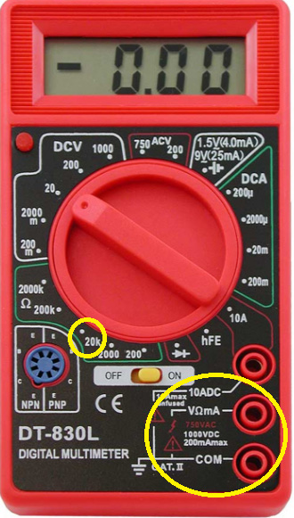
Start by setting your multimeter to measure resistance. Some meters set their range automatically, while some need to be set manually. If your meter requires manual ranging, select the 20k ohm setting. If it auto-ranges, turn the dial to Ohms.
Ensure you plug the red test lead into the port labeled with the Ohms symbol (Ω) and the black lead into the port labeled COM. See the photo for an example of the correct setting and which ports to use.
Measure the Actuator Cable
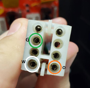
Next, you will measure the resistance between the three wire pairs inside the actuator plug. The wires you will test are green, orange, and white. Insert one lead into each of the listed wires in the plug. It does not matter which multimeter lead touches which wire.
Once both leads make contact with a pair, note the resistance reading on the display. You will compare these three readings against the actuator stroke length in the next step.
Using your multimeter leads, check each combination:
- Green to Orange
- Green to White
- Orange to White
Please note that your meter may display 'OL' or '1.' when taking these measurements. This could mean your range setting on the meter is not set correctly.
Measure the Stroke Length of the Actuator
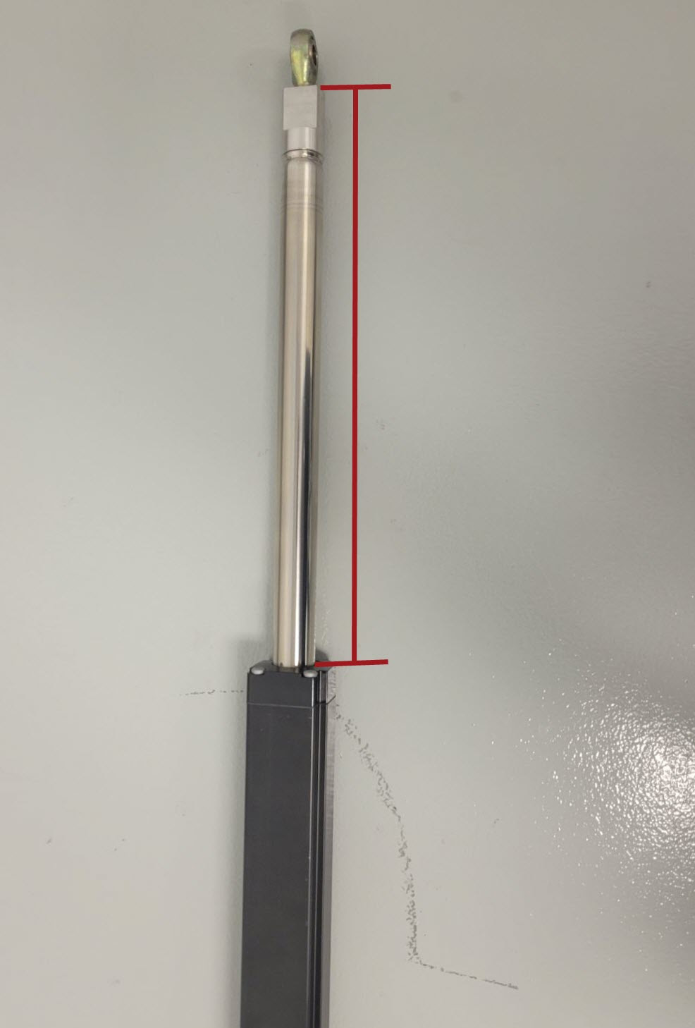
The green-to-orange measurement should read about 10k Ohms. The orange-to-white and white-to-green readings should also add up to roughly 10k Ohms combined. Keep in mind that these values will shift depending on where the actuator arm is currently positioned.
Example of acceptable readings:
- Green to Orange: 10.01k
- Green to White: 1.33k
- Orange to White: 8.68k
If your readings align with what’s listed above, compare your white-to-green measurement to the stroke length chart. This reading indicates the arm's current position, so it will vary as the actuator extends or retracts.
| Extension Rod Length | Green to White Measurement |
|---|---|
| 2.5 | 0.91 |
| 3 | 1.092 |
| 4 | 1.332 |
| 5 | 1.6 |
| 6 | 1.82 |
| 7 | 2.08 |
| 8 | 2.33 |
| 9 | 2.58 |
| 10 | 2.83 |
| 11 | 3.08 |
| 12 | 3.32 |
| 13 | 3.57 |
| 14 | 3.82 |
| 15 | 4.06 |
| 16 | 4.32 |
| 17 | 4.57 |
| 18 | 4.81 |
| 19 | 5.06 |
| 20 | 5.32 |
| 21 | 5.56 |
| 22 | 5.83 |
| 23 | 6.06 |
| 24 | 6.29 |
| 25 | 6.57 |
Shop the Ranger HD Actuator
If you need further assistance, give us a call! We’ll be happy to assist you in any way we can with your USAutomatic Gate Opener.
Contact Us